Sunday, October 20, 2013
How to Check a Cylinder Bore

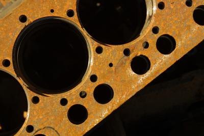
Cylinder bores must fall within specific, factory-set tolerances to be considered useable. Check cylinders for visible damage and measure using precision measuring equipment such as micrometers and dial-bore indicators. Measurements taken at specific points of the bore indicate cylinder taper and out-of-round conditions that require machining to correct. Checking a cylinder bore requires knowledge of the proper use of the precision measuring equipment as well as the factory specifications as set by the manufacturer. Disassemble the engine to remove the cylinder head and pistons prior to checking the cylinder bore.
Instructions
- 1
Visually inspect the cylinder for signs of lateral scoring, galling and partial piston seizure.
2Feel the top of the cylinder for a shoulder using your fingernail. The shoulder will form right at the top of the unswept portion of the cylinder bore above where the top compression ring ceases to travel upwards. Hone the cylinder to remove the shoulder, if one is present.
3Install an arbor on the dial-bore indicator so the plunger on the indicator is roughly in the center of its travel when placed within the bore.
4Set an outside micrometer to the small end of the cylinder diameter specification as indicated by the manufacturer. Record the micrometer setting on a piece of paper.
5Place the dial-bore indicator in the micrometer and rotate the bezel on the indicator gauge until the zero aligns with the needle. Remove the indicator from the micrometer.
6Measure the top of the cylinder on the X axis using the dial-bore indicator. Record the number indicated by the gauge and add that number to the micrometer setting number. Record the final sum. Repeat this process on the Y axis at the top of the cylinder. Record the final sum next to the top X axis number.
7Repeat the process in the middle and at the bottom of the bore, pairing the X and Y axis measurements together.
8Compare the X and Y axis number pairs. A difference in the bore diameter within any given pair indicates an out-of-round condition.
9Compare the top, middle and bottom number pairs. A difference in the bore diameter between the position groups indicate a cylinder taper condition.
10Measure the outside diameter of the piston skirt even with, and 90 degrees from, the wrist pin boss area. Compare the piston diameter to the largest and smallest bore diameter to determine the piston-to-cylinder clearance range.
11Compare all measurements to the manufacturers tolerances to determine whether the bore is within service specifications or if machine work is needed.
No comments:
Post a Comment